|

|
|
|
|
|
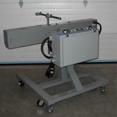
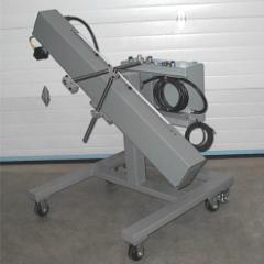
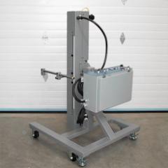
# M5 Single Axis Tilting Traverse |
|
|
|
|
|
|
|
|
|
|
|
|
|
|
|
|
|
|
|
|
|
|
|
|
|
|
|
|
|
|
|
|
|
|
|
|
|
|
|
|
|
|
|
|
|
|
|
|
|
|
|
|
|
|
|
|
|
|
|
|
|
|
|
|
|
|
|
|
|
# M5 Single Axis Tilting Traverse |
|
|
|
|
| 1 |
GENERAL DESCRIPTION |
|
|
|
|
|
The
AJRM5 Single Axis Tilting Traverse Unit is designed for use with all |
|
|
flame
spray guns and equipment. It is
capable of providing control of speed |
|
|
and
length of stroke along a single axis.
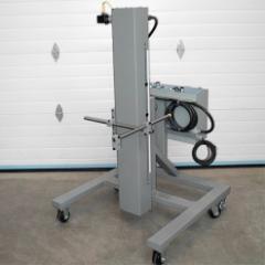
The direction of that axis can be |
|
|
adjusted
to horizontal, vertical, or points between.
The control panel |
|
|
provides for convenient control of all parameters. |
|
|
|
|
|
Performance Capabilities |
|
|
|
|
|
The
unit is capable of satisfying the needs of an extensive range of |
|
|
applications. Two
programs are included: |
|
|
|
|
| A. |
LL 3 --------------- 2
--------------- 1 RL |
|
|
|
|
|
left limit
spray rapid right limit |
|
|
|
|
|
| B. |
LL 3
======== 2 --------------- 1 RL |
|
|
|
|
|
Standard Programs |
|
|
|
|
|
Program A: For
standard cylindrical work. |
|
|
|
|
| - |
Move from right limit to 1 and stop |
|
| - |
Operator activates RUN button |
|
| - |
Move from 1 to 2 at rapid speed |
|
| - |
Move from 2 to 3 and back to 2 at spray speed |
|
| - |
Repeat above step until counter is satisfied |
|
| - |
When counter is satisfied, return to 1 and stop. |
|
|
|
|
|
Program B: For
spraying blind bores. |
|
|
|
|
| - |
Move from right limit to 1 and stop |
|
| - |
Operator activates RUN button |
|
| - |
Move from 1 to 2 at rapid speed |
|
| - |
Move from 2 to 3 at rapid speed |
|
| - |
Move from 3 to 2 at spray speed |
|
| - |
Repeat above 2 steps until counter is satisfied |
|
| - |
When counter is satisfied, return to 1 and stop. |
|
|
|
|
|
Controls |
|
|
|
|
|
On the Traverse Unit: |
|
|
|
|
| - |
The left and right limits are fixed |
|
| - |
Limit switches 1, 2 and 3 are all adjustable |
|
| - |
Distance between fixed limits is 40”. |
|
|
|
|
|
On the Control Panel: |
|
|
|
|
| - |
Power On/Off and Emergency Stop |
|
| - |
Power indicator light |
|
| - |
Program abort or home button |
|
| - |
Reset able mechanical counter |
|
| - |
Individual speed controls for rapid, spray and jog |
|
| - |
Jog buttons for forward and reverse |
|
| - |
Program selector. |
|
|
|
|
|
Mechanical Limitations |
|
|
|
|
|
The traversing unit will operate within the following
mechanical limitations: |
|
|
|
|
| - |
Maximum traverse length:
40” |
|
| - |
Minimum traverse speed:
2-1/2” per minute |
|
| - |
Maximum traverse speed:
50” per minute |
|
| - |
Alternate traverse speeds available upon request |
|
| - |
Maximum gun weight:
40 pounds |
|
| - |
Gun mount infinitely adjustable |
|
| - |
Working height approximately 40” above the floor |
|
| - |
Fixed unit provided with a sturdy base |
|
| - |
Portable unit provided with casters and floor locks |
|
| - |
Locked positions at horizontal and vertical |
|
|
|
|
|
|
|
| 2 |
REQUIRED FACILITIES |
|
|
|
|
|
The
AJRM5 Tilting Traverse Unit operates on 110 Volt, 60Hz. electrical |
|
|
power
provided through the plug on the electronic control panel. The outlet |
|
|
used
must be fused to a minimum of 15 amps and should be on a circuit free |
|
|
of electrical interference. |
|
|
|
|
| 3 |
INSTALLATION |
|
|
|
|
|
The
control panel will be connected to the traverse unit with a heavy duty |
|
|
cable
approximately 15 feet in length. The
control panel should be mounted |
|
|
on
a wall or the side of the spray booth close enough to the spray area to |
|
|
allow
full required movement of the traverse unit.
The control panel will |
|
|
also
have to be plugged into a 110 Volt outlet.
The electrical cord is |
|
|
approximately 9 feet. |
|
|
|
|
|
With
the power switched off at the control panel, attach the free end of the |
|
|
heavy
duty cable to the amphenol connector on the traverse unit. The unit is |
|
|
ready to operate. |
|
|
|
|
| 4 |
OPERATION |
|
|
|
|
|
Program A: |
|
|
|
|
|
#1, #2, and #3 are movable limit switches |
|
|
|
|
|
LL #3 --------------- #2
--------------- #1 RL |
|
|
|
|
|
left limit
spray rapid right limit |
|
|
|
|
| - |
Move from right limit to 1 and stop |
|
| - |
Operator activates START button |
|
| - |
Move from 1 to 2 at rapid speed |
|
| - |
Move from 2 to 3 and back to 2 at spray speed |
|
| - |
Repeat above step until counter is satisfied |
|
| - |
When counter is satisfied, return to 1 and stop. |
|
|
|
|
|
The
above program is designed to spray standard cylindrical work. Use the |
|
|
following steps: |
|
|
|
|
| 1 |
Set #3 limit switch to farthest spray position. |
|
| 2 |
Set #2 limit switch to nearest spray position. |
|
| 3 |
Set #1 limit switch to desired home position. |
|
| 4 |
Turn power switch on. |
|
| 5 |
Press on button. |
|
| 6 |
Press
and hold suitable jog button to move spray gun first to near the |
|
|
right
limit and then to the farthest spray position. Use the Jog Speed |
|
|
Control Knob to increase or decrease speed. |
|
| 7 |
Fine
tune the position of the #3 limit by aligning the black knob with |
|
|
the upright post |
|
| 8 |
Press
and hold the reverse jog button to move spray gun to the right |
|
|
most spray position.
Fine tune the position of the #2 limit. |
|
| 9 |
Press
and hold the reverse jog button to move spray gun to the desired |
|
|
home position. Fine
tune the position of the #1 limit. |
|
| 10 |
Reset
the pass counter to “0” by pressing the black button at the left of |
|
|
the top set of numbers. |
|
| 11 |
Reset
the set point to “0,0,0” by holding down the white lever at the |
|
|
left
of the lower set of numbers and pressing the black buttons under |
|
|
the numbers until returning to “0”. |
|
| 12 |
Run
the program through one cycle to check for clear operation and to |
|
|
set
spray and rapid speeds. Press and
hold the Start Button for 1 to 2 |
|
|
seconds. This will
start the unit to run one pass. |
|
| 13 |
Set
the rapid speed using the Rapid Speed Control Knob while the |
|
|
traverse is operating between switches #1 and #2. |
|
| 14 |
Set
the spray speed using the Spray Speed Control Knob while the |
|
|
traverse is operating between switches #2 and #3. |
|
| 15 |
The
traverse will stop when it returns to the home position. Adjust the |
|
|
set point to the desired number of passes. Reset the counter. |
|
| 16 |
Press
and hold the start button for 1 to 2 seconds. The traverse unit |
|
|
will
complete the set number of passes and return to the home |
|
|
position. |
|
| 17 |
At
any time during execution of the program, you can press the |
|
|
Abort/Home
Button. This will allow the traverse
to complete the |
|
|
current pass and then return to the home position. |
|
| 18 |
At
any time during execution of the program, you can press the Red |
|
|
Emergency
Stop Mushroom Button. This will stop
the traverse |
|
|
immediately. To restart, you must press the On Button
and then the |
|
|
Start Button. The
program will restart where it was interrupted. |
|
|
|
|
|
|
|
|
Program B: |
|
|
|
|
|
#1, #2, and #3 are movable limit switches. |
|
|
|
| B. |
LL #3
======== #2 --------------- #1 RL |
|
|
|
|
left limit
spray rapid right limit |
|
|
|
|
|
| - |
Move from right limit to 1 and stop |
|
| - |
Operator activates RUN button |
|
| - |
Move from 1 to 2 at rapid speed |
|
| - |
Move from 2 to 3 at rapid speed |
|
| - |
Move from 3 to 2 at spray speed |
|
| - |
Repeat above 2 steps until counter is satisfied |
|
| - |
When counter is satisfied, return to 1 and stop. |
|
|
|
|
The
above program is designed to spray blind bores or for other applications |
|
|
where
separate speed control is required over each spray direction. Use the |
|
|
same procedures as above but with the program selector on
“B”. |
|
|
|
|
|
|
|
|
|
|
|
|
|